
1. Why Are Tungsten Carbide Burrs Used for Robotic Deburring?
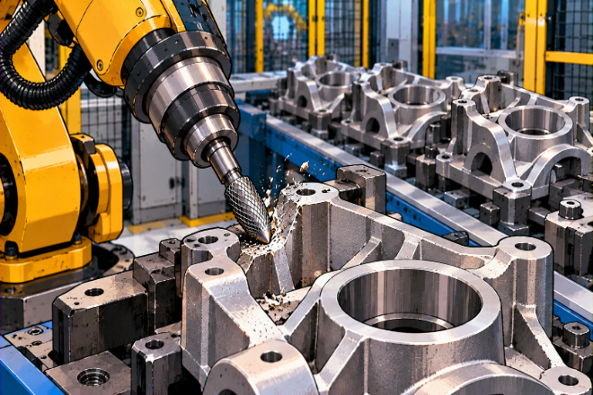
Deburring sounds simple until a factory has to process hundreds or thousands of parts. A manual operator may adjust pressure, angle, and movement naturally.
A robot cannot simply “feel” that something looks wrong. It needs a stable tool, a clear path, and repeatable cutting conditions.
这就是 tungsten carbide burrs become useful.
A carbide burr has defined cutting teeth that remove material as the tool rotates. It can be used for deburring, leveling, edge work, hole cleanup, and surface work.
Its geometry stays relatively consistent during its useful life, which is important when a robot repeats the same movement many times.
For robotic applications, tool stability is especially important.
High concentricity can reduce unwanted vibration and chatter, while the correct burr geometry can help the robot follow a programmed contour more smoothly.
The biggest benefit is therefore not simply cutting speed.
It is repeatability.
If the robot uses the same tool, follows the same path, and works under controlled conditions, each part can receive a much more consistent edge treatment.
That can reduce manual finishing, improve cycle consistency, and make quality easier to monitor.
2. What Types of Parts Can Robots Deburr with Carbide Burrs?
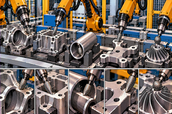
Robotic carbide burrs are useful when parts have repeated edges, cast surfaces, weld areas, holes, or other locations where unwanted material must be removed.
Typical applications include cast metal components, fabricated parts, machined components, 汽车 parts, industrial housings, pipes, and other metal assemblies.
The burr can remove:
Casting flash
Small burrs around machined holes
Sharp edges
Weld residue
Excess material around openings
Uneven transitions
Local surface buildup
Material around complex contours
The exact application depends on the part material and geometry.
For steel parts, a suitable steel-cut burr can provide strong material removal. Stainless steel may need a cut designed for stainless materials.
Aluminum presents a different challenge because soft metal can load the cutting teeth. Material-specific carbide burrs are available for these different conditions.
Composite parts can also be processed with specialized carbide burrs. Some geometries are designed to reduce fraying and delamination during robotic trimming and deburring.
For production managers, this leads to an important point:
The robot does not need one universal burr for every part.
A better system uses a burr that matches the material, edge condition, and required finish.
3. How Should You Choose a Carbide Burr for a Robotic Deburring Cell?
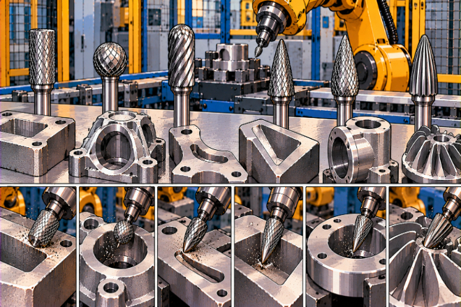
Tool selection should start with the part—not with the burr catalog.
First, look at the material. Steel, stainless steel, aluminum, cast iron, titanium, and reinforced plastics can require different cutting designs.
Next, examine the edge.
Is the robot removing a small sharp edge?
Is it removing heavy casting flash?
Does it need to follow a curved contour?
Is it working inside a hole?
Does the final edge need a simple break, a chamfer, or a defined radius?
These questions determine the burr shape.
A cylindrical burr is useful for relatively open surfaces. A ball or radius-end burr can follow curved areas.
Cone and tree shapes can reach narrow areas, while special radius or edge-working burrs can help create more controlled edge shapes.
Defined-edge carbide burr systems are specifically designed for chamfering, deburring, and rounding operations.
For robotic production, a special burr shape can sometimes reduce the number of tool changes.
One specialized robot burr can combine different working geometries, allowing several edge operations to be completed with fewer tools.
Tool selection can be viewed simply:
4. How Does a Robot Control a Tungsten Carbide Burr?
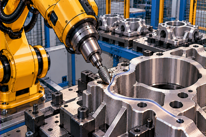
A robot does not simply move the burr from point A to point B.
For good deburring, several conditions need to work together: tool position, travel path, feed rate, spindle speed, contact pressure, approach angle, and workpiece location.
The first step is usually to define the edge or surface that needs treatment. The robot then follows a programmed path while the rotating burr removes material.
Tool contact is especially important.
If too much of the burr is pressed into the workpiece, cutting can become rough and unstable.
General carbide burr guidance recommends limiting the contact area and using suitable cutting conditions to avoid poor cutting behavior and broken teeth.
Robot programming should also avoid sudden changes in direction. A smooth path usually produces a more stable cutting action than a path full of sharp movements.
Workholding is another hidden part of the process.
Imagine a robot perfectly following the same path 5,000 times—but the workpiece moves slightly every time. The robot is consistent, but the result is not.
That is why fixtures, part location, tool concentricity, and robot calibration all matter.
The goal is to make the entire system repeatable: Part position → Robot path → Tool contact → Material removal → Final edge
When one link changes, the final result can change as well.
5. How Should You Set Speed, Feed, and Cutting Conditions?
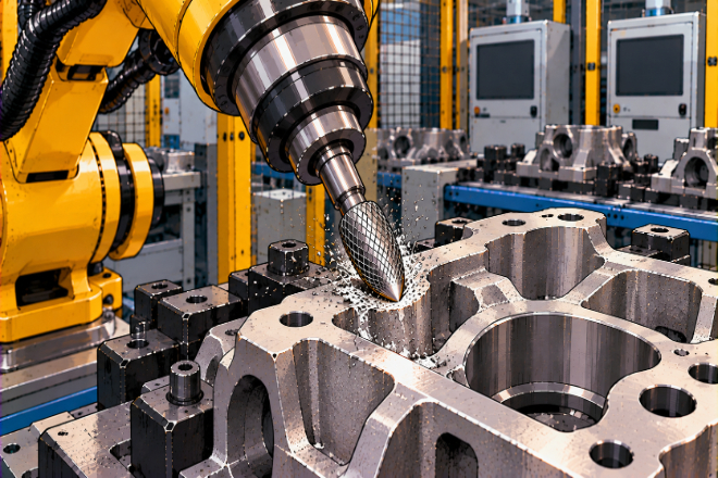
There is no single RPM that works for every robotic deburring application.
The correct rotational speed depends on factors such as material, burr diameter, cut type, and whether the operation is heavy stock removal or light finishing.
This is particularly important in automation because the robot may run continuously for long periods.
A poor setting that seems harmless during a short test can become expensive when repeated thousands of times.
If the speed is too low, the burr may cut poorly and increase cycle time.
If the speed is too high for the selected tool and application, heat, wear, or control problems can increase.
Feed rate also matters. Moving too slowly can keep the burr in one area for too long. Moving too quickly can reduce material removal and leave an unfinished edge.
A good production setup should therefore test several combinations instead of choosing settings by guesswork.
Start with the tool’s recommended operating range, then check:
Edge quality
Cycle time
Tool wear
Vibration
Surface condition
Burr size after processing
Number of parts per tool
For robotic systems, the best setting is not always the one with the highest cutting speed. It is the one that gives the required edge quality at a stable cost per part.
6. How Can Companies Improve Robotic Deburring Results?

Once the robot is running, the next challenge is keeping the process stable.
Tool wear is one of the first things to monitor.
A carbide burr does not suddenly become useless one morning. Its performance normally changes over time. The edge may become less effective, material removal may slow, or the finished surface may become different.
For this reason, companies should create a tool-change rule based on actual production results.
Useful measurements include: Parts per burr + cycle time + edge quality + rework + tool cost
This is much more useful than changing every burr after an arbitrary number of cycles.
The robot program should also be standardized. Operators should not need to manually adjust the path every time a burr is replaced.
If tool geometry changes significantly, the programmed path may no longer produce the same result. Tool dimensions, runout, fixture position, and tool mounting should therefore be checked when setting up a new production run.
Another useful improvement is reducing tool changes.
Special robot burrs with combined geometries can sometimes perform multiple deburring or chamfering operations in one pass, reducing programming work and tool-change time.
However, longer does not always mean better. Long-shank carbide burrs require special care and are not suitable for some robotic or stationary applications because bending can increase the risk of breakage.
A simple production review every few weeks can reveal surprising opportunities.
Sometimes the biggest improvement does not come from buying a faster burr. It comes from changing the burr shape, fixture, path, or replacement rule.
 English
  Español
  简体中文
简体中文  Français
  日本語
日本語  한국어
한국어  العربية
  Tiếng Việt